Raspberry Pi I2C Temperature Sensor
Atlas Scientific Temperature Sensor
There are several temperature sensors that are available for your Raspberry Pi one of the most popular being the DS18B20, however if you are looking for an I2C connected temperature sensor then the Atlas Scientific RTD Temperature sensor is an excellent option. If your project already involves the use of other I2C sensors then this can be easily added in parallel without using any additional GPIO pins on your Pi. This sensor also provides on board logging capabilities and provides readouts in either Celsius, Fahrenheit or Kelvin, with the addition of a thermowell you will be able to insert your temperature probe into your plumbing.
To configure the RPi I am assuming that you are running the latest version of Raspian and have the ability to connect to your Pi either through SSH with putty and FTP with filezilla, or directly with a keyboard and monitor, if you haven’t set-up your RPi yet then check out my getting started section.
The first thing we need to do is enable the I2C modules on the RPi. This is done by entering the following at the command prompt to start the configuration tool.
select option 9 – Advanced Options
select option A7 – I2C
select “Yes” for all the questions and reboot the RPi
After the reboot connect to the command prompt and enter
sudo apt-get install i2c-tools
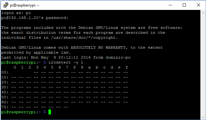
i2cdetect -y 1
This should produce the following without the sensor attached.
Now that we have our I2C module working correctly we can go ahead and connect our temperature sensor. The following materials will be needed to get started:
- Raspberry Pi
- Atlas Scientific Temperature sensor kit
- Breadboard
- Jumper Wires
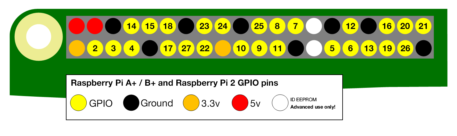
When describing the physical pin connections I will be following the GPIO pin numbering convention show below.
Firstly we need to get the temperature circuit into the correct mode, when delivered the temperature circuit will be in UART (serial) mode, the temperature circuit has to be manually switched from UART mode, to I2C mode. When this is done the temperature circuit will have its I2C address set to 102 (0x66).
Using your breadboard perform the following actions
- Cut the power to the device
- Disconnect any jumper wires going from TX and RX to the RPi
- Short the PGND pin to the TX pin
- Power the device
- Wait for LED to change from Green to Blue
- Remove the short from the probe pin to the TX pin
- Power cycle the device
The device is now I2C mode.
The RPi and temperature circuit are now configured so we can go ahead and connect it all together
Assuming that all of the parts are now mounted on your breadboard
- Connect the GND pin of the temperature circuit to the ground pin of your RPi.
- Connect the TX(SDA) pin to GPIO pin 2.
- Connect the RX(SCL) pin to GPIO pin 3.Do Not Use jumper wires for these connections or your readings will not be accurate.
- The PRB and PGND pins should be connected via your breadboard to the centre and shield pins of your BNC connector.
- Finally power your temperature circuit by connecting the Vcc pin to the +3.3V pin.
You can now run a quick test to prove that we are setup correctly, from the command prompt enter the following:
you should see the following response, if not then check you connections, ensure the light on the temperature circuit is blue and reboot your RPi.
In the image above I have 4 sensors connected to my RPi, the Temperature sensor connection is indicated by Hex value 66. The factory preset address for the pH sensor is 102 or 66 in hexadecimal as mentioned above, if you have more than 1 temperature circuit connected then you will need to specify a different value. To do this we need to add some python code to our RPi.
Atlas Scientific provide the python code that I will be using here for interfacing with the temperature circuit.
We start by importing the required python modules
import io # used to create file streams
import fcntl # used to access I2C parameters like addresses
import time # used for sleep delay and timestamps
import string # helps parse strings
Next we add the class code to interface with the temperature circuit (or any other Atlas Scientific circuit for that matter)
class atlas_i2c:
long_timeout = 1.5 # the timeout needed to query readings & calibrations
short_timeout = .5 # timeout for regular commands
default_bus = 1 # the default bus for I2C on the newer Raspberry Pis,
# certain older boards use bus 0
default_address = 102 # the default address for the Temperature sensor
def __init__(self, address=default_address, bus=default_bus):
# open two file streams, one for reading and one for writing
# the specific I2C channel is selected with bus
# it is usually 1, except for older revisions where its 0
# wb and rb indicate binary read and write
self.file_read = io.open("/dev/i2c-" + str(bus), "rb", buffering=0)
self.file_write = io.open("/dev/i2c-" + str(bus), "wb", buffering=0)
# initializes I2C to either a user specified or default address
self.set_i2c_address(address)
def set_i2c_address(self, addr):
# set the I2C communications to the slave specified by the address
# The commands for I2C dev using the ioctl functions are specified in
# the i2c-dev.h file from i2c-tools
I2C_SLAVE = 0x703
fcntl.ioctl(self.file_read, I2C_SLAVE, addr)
fcntl.ioctl(self.file_write, I2C_SLAVE, addr)
def write(self, string):
# appends the null character and sends the string over I2C
string += "�0"
self.file_write.write(string)
def read(self, num_of_bytes=31):
# reads a specified number of bytes from I2C,
# then parses and displays the result
res = self.file_read.read(num_of_bytes) # read from the board
# remove the null characters to get the response
response = filter(lambda x: x != 'x00', res)
if(ord(response[0]) == 1): # if the response isnt an error
# change MSB to 0 for all received characters except the first
# and get a list of characters
char_list = map(lambda x: chr(ord(x) & ~0x80), list(response[1:]))
# NOTE: having to change the MSB to 0 is a glitch in the
# raspberry pi, and you shouldn't have to do this!
# convert the char list to a string and returns it
return "Command succeeded " + ''.join(char_list)
else:
return "Error " + str(ord(response[0]))
def query(self, string):
# write a command to the board, wait the correct timeout,
# and read the response
self.write(string)
# the read and calibration commands require a longer timeout
if((string.upper().startswith("R")) or
(string.upper().startswith("CAL"))):
time.sleep(self.long_timeout)
elif((string.upper().startswith("SLEEP"))):
return "sleep mode"
else:
time.sleep(self.short_timeout)
return self.read()
def close(self):
self.file_read.close()
self.file_write.close()
Finally we will add our main program
def main():
    device = atlas_i2c()  # creates the I2C port object, specify the address
                          # or bus if necessary
    print ">> Atlas Scientific sample code"
    print ">> Any commands entered are passed to the board via I2C except:"
    print (">> Address,xx changes the I2C address the Raspberry Pi "
    "communicates with.")
    print (">> Poll,xx.x command continuously polls the board every "
    "xx.x seconds")
    print (" where xx.x is longer than the %0.2f second "
    "timeout." % atlas_i2c.long_timeout)
    print " Pressing ctrl-c will stop the polling"
    # main loop
    while True:
        myinput = raw_input("Enter command: ")
        # address command lets you change which address
        # the Raspberry Pi will poll
        if(myinput.upper().startswith("ADDRESS")):
            addr = int(string.split(myinput, ',')[1])
            device.set_i2c_address(addr)
            print ("I2C address set to " + str(addr))
        # contiuous polling command automatically polls the board
        elif(myinput.upper().startswith("POLL")):
            delaytime = float(string.split(myinput, ',')[1])
            # check for polling time being too short,
            # change it to the minimum timeout if too short
            if(delaytime < atlas_i2c.long_timeout):
                print ("Polling time is shorter than timeout, setting "
                "polling time to %0.2f" % atlas_i2c.long_timeout)
                delaytime = atlas_i2c.long_timeout
            # get the information of the board you're polling
            info = string.split(device.query("I"), ",")[1]
            print ("Polling %s sensor every %0.2f seconds, press ctrl-c "
            "to stop polling" % (info, delaytime))
            try:
                while True:
                    print device.query("R")
                    time.sleep(delaytime - atlas_i2c.long_timeout)
            except KeyboardInterrupt:  # catches the ctrl-c command,
                                       # which breaks the loop above
                print "Continuous polling stopped"
        # if not a special keyword, pass commands straight to board
        else:
            try:
                print device.query(myinput)
            except IOError:
                print "Query failed"
if __name__ == '__main__':
    main()
All of this python code is available for both 2.x and 3.x on my HydroPi GitHub repository.
We now transfer our code to our chosen folder on the RPi using an FTP client and then run the program.
The screenshot above shows that we are ready to start sending commands to our temperature circuit, to confirm that sensor is now fully functioning we will enter the following command
This will poll the sensor every 2 seconds and return the result until a ctrl-c command is entered as shown below, to stop the program enter ctrl-c again.
With the sensor now working there are also a series of other commands that we now have available to us to configure our probe. Above I have shown how to change the reading from Celsius to Fahrenheit.
Enable/disable the LED on the Temperature circuit:
L,1 - LED enable
L,0 - LED disable
L,? - Query the LED
Set the temperature scale required for output:
S,C - Sets the output of the sensor to Celsius (Default)
S,F - Sets the output of the sensor to Fahrenheit
S,K - Sets the output of the sensor to Kelvin
S,? - Queries the output temperature scale.
Take a single reading:
R - Returns a single result
Calibration:
The temperature circuit can be calibrated using a single point calibration. While this is possible RTD temperature senors have very predictable behaviour at varying temperatures, because of this fact calibration is not absolutely required.
Cal,n - Where n is any
Cal,clear - Clears all calibration data
Cal,? - Query the calibration
Circuit Address Change:
I2c,n - n is the new decimal address
Changes to the address of the circuit will cause a loss of connectivity until the python script is restarted with the new address.
Info, Status, Low Power and Factory Reset:
I - Device information
STATUS - Reports reason for last reboot and Vcc voltage
FACTORY - Factory reset. This will not change the communications protocol back to UART.
SLEEP - Enter low power sleep state.
The Temperature sensor circuit also provides for some additional settings that allow for the use of it’s internal data logger (up to 50 readings) and the protocol lock feature. For more information on configuration of the temperature circuit read this.
There we have it, you have now configured your RPi to interface with the Atlas Scientific Temperature Sensor.
Any thought’s, improvements or errors let me know in the comments below.


I used to be an embedded system designer. Interfacing I2C devices used to involve coding at the lowest level, i.e. driving the I2C pin itself. I’ve got an RPi2 with me but I haven’t really started anything on it. I suppose it doesn’t involve any low-level coding anymore? Maybe just a line of code/script to initialise and read the values?
Thanks Kenny
The Pi’s make it incredibly easy to add these sensors, just enable the I2C functionality from the configuration menu and they are virtually Plug and Play. Atlas Scientific even provide the python code to get you started.