Connect an LED and Button to a Raspberry Pi
Simple Raspberry Pi GPIO Circuits
Interacting with electronic circuits is one of the great things you can do with the Raspberry Pi, utilising it’s General Purpose Input Output (GPIO) ports. If you are new to making electronic circuits then you do need to be careful as it is possible to damage your Pi by applying too much voltage to or drawing too much current from the pins. There are many Raspberry Pi beginner projects and here I will show you how to safely connect an LED and button to the GPIO pins and then control the LED using the button. While these circuits and the python code are quite simple controlling inputs and outputs is a great place to start before tackling more complicated projects.
Basic Materials
Electronics
- LED
- SPST (Single Pole Single Throw) micro push button switch
- 330Ω Resistor
- BS270 Field Effect Transistor (FET) or equivalent
Connecting A LED to a Raspberry Pi
Connecting a Light Emitting Diode (LED) is one of the things most people try when first building a circuit on the Pi. LED’s are like other diodes in that they will only allow current to flow in one direction and require a minimum voltage to “turn on”, once the LED is turned on the flowing current is converted to light and this is what we see. They come in several different colours, the most common being red, orange, yellow and green which all require a different amount of voltage to turn on. When connecting a LED to your Pi it is important to ensure you always have a resistor in series to prevent large currents flowing as this will very quickly burn out your LED.
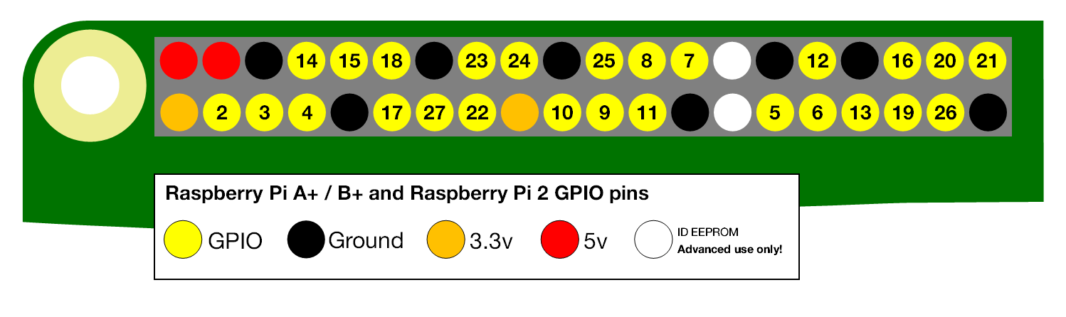
In the following examples I will use the Broadcom pin numbering convention as shown below, as that is what is shown on the T-Cobbler.
 Most common LED’s require a forward (turn on) voltage of between 1.2 – 3.6V depending on the color and a current of 10 to 30mA with 12 to 20mA being common. So to calculate the resistor value that we require we use the simple Voltage = Current x Resistance (V=IR) formula, or in this case R=V/I. So assuming that we are using a Red LED that requires a forward voltage of 1.8V and that we want a maximum current of 10mA.
Resistance = (Source Voltage – LED Forward Voltage) / Max Current
Resistance = (5V – 1.8V) ⁄ 0.01A
Resistance = 320Ω
If you wanted a maximum current of 20mA then you would replace 0.01 with 0.02 and end up with a resistor value of 160Ω, these are minimum values so you would select the next highest standard resistor value. It should be noted that the Pi’s 5V power supply can provide approximately 200 – 300mA, this should be considered when adding multiple LED’s to a circuit.
Increasing the size of the resistor would drop the current and dim the LED, this however is not recommended and you should probably never drop the current below 5mA as the LED may turn off completely. To dim an LED properly you should use the PWM facilities of the Pi but that is beyond what I am going to discuss in this article.
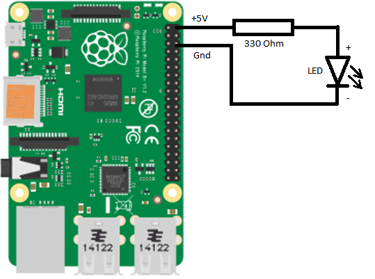
To start, shutdown your Pi, the simplest circuit we can then make is to connect the 5V pin of the Pi to a 330 Ohm resistor and then through the LED and back to Ground (GND). As mentioned earlier the LED will only pass current in one direction so it needs to be placed in the circuit the right way round. Current passes from positive to negative through the LED, the shorter leg of the LED is the negative one, if you have cut the legs down too the same length the other way of identifying the polarity is that the resin body itself will have a notch or flat spot on the negative side.
Once you have built and double checked your circuit restart your Pi and the LED will illuminate.
Now we have working LED circuit we can add some control with the GPIO’s. A GPIO pin on the Pi can safely provide (source) a maximum 16mA of current. As you can see above if we choose an appropriate resistor value then a LED could be connected directly to a GPIO pin without sourcing too much current.
The Pi 3.3V supply was designed to supply a current of 3mA per GPIO pin. If you load each pin with 16mA the total current sourced on a Pi 3 would be 416mA and the 3.3V supply could fail under those conditions. To ensure we do not damage the Pi we should try to keep the current as low as possible (1-3mA).
Controlling the LED
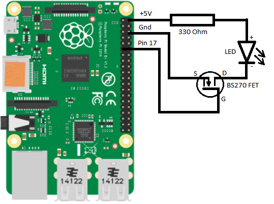
A better solution is to use a Field Effect Transistor (FET) as a switch to turn on the LED. We can take the existing circuit and add the FET by connecting the Drain to the -ve leg of the LED, connect the Gate to GPIO pin 17 and connect the source back to Ground. This will allow us to apply a voltage to the gate of the FET which will close the connection between the Drain and Source and allow current to flow through the LED. The advantage of this is that the FET draws almost no current from the Pi’s GPIO pin to achieve this.
The following python code will blink the led every 0.1 seconds (10Hz), I am using the RPi.GPIO python library to control the GPIO, another good option is WiringPi but it does not come standard on the Pi and you will need to import it.
#!/usr/bin/env python
import RPi.GPIO as GPIO  # Import RPi.GPIO Module
from time import sleep  # Import sleep Module for timing
GPIO.setmode(GPIO.BCM)  # Configures pin numbering to Broadcom reference
GPIO.setwarnings(False)  # Disable Warnings
GPIO.setup(17, GPIO.OUT)  #Set our GPIO pin to output
GPIO.output(17, False)  #Set output to off
while (True):
        GPIO.output(17, True)  # Turn LED on
        sleep(0.01)
        GPIO.output(17, False) # Turn LED off
        sleep(0.01)
Connecting A Button to A Raspberry Pi
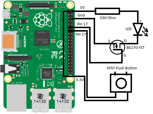
Finally we will add a button to the circuit and configure one of the GPIO pins to act as an input, we will use the button to start and stop the blinking LED. The GPIO pins on the Pi can accept up to 3.3V as an input so the circuit will go between the 3.3V output of the Pi, through the button and back to GPIO pin 27 as shown below, we do not need to touch our existing LED circuit.
We do not need a dedicated pull-down resistor in this circuit as all the GPIO pins on the Pi have software configured pull-up/pull-down resistors that have a default setting at startup. Pin 27 is set as pull-down by default which will stop any spurious voltages triggering the circuit. As a precaution though you should set the pin in software to pull-down just to be certain.
The following python code will set the pull down resistor on pin 27 and then wait for a button push by detecting the rising edge of the input voltage. Due to the mechanical nature of a button the connection is not smooth and will “bounce” when first making contact, to overcome this we can use the RPi.GPIO library to “de-bounce” the button by waiting 200ms after it detects the change before deciding whether the input is high or low.
#!/usr/bin/env python
import RPi.GPIO as GPIO  # Import GPIO Module
from time import sleep  # Import sleep Module for timing
GPIO.setmode(GPIO.BCM)  # Configures pin numbering to Broadcom reference
GPIO.setwarnings(False)  # Disable Warnings
GPIO.setup(17, GPIO.OUT)  #Set our GPIO pin to output
GPIO.output(17, False)  #Set output to off
GPIO.setup(27, GPIO.IN, pull_up_down=GPIO.PUD_DOWN)  # Set GPIO to input with a  pull-down resistor
GPIO.add_event_detect(27, GPIO.RISING, bouncetime=200)  # Monitor GPIO pin for a rising edge and debounce for 200mS
while (True):
    if GPIO.event_detected(27):  # Check to see if button has been pushed
        activate = True
        while (activate is True):  # Execute this code until the button is pushed again
            GPIO.output(17, True)  # Turn LED on
            sleep(0.01)
            GPIO.output(17, False) # Turn LED off
            sleep(0.01)
            if GPIO.event_detected(27):  # Check for a 2nd button push
                activate = False
    else:
        GPIO.output(17, False)  # Turn LED off
With the code running we now have the ability to control the LED using the button attached to an input GPIO pin. While this is quite a simple example of controlling external circuits using the GPIO pins it has many applications in more complex projects.
As final note it is always good practice to execute a cleanup when your code has completed
This will return all of the channels you have used in your code back to inputs with no pull up/down resistors, this will help you to avoid causing accidental damage to the Pi or having conflicts with other code.
If you have any thought’s about this article, improvements or errors let me know in the comments below and if you found this helpful, why not share it with others.
Interesting; I went to the Raspberry Pi Foundation site to get a little bit more if into. I never knew this was a popular thing to create these devices.
Would you say Raspberry Pi is used in robotics a lot? I imagine it’s pretty multifaceted, but I’m just guessing.
Also, how much does it cost to put one of these together? Assembly seems straightforward enough, for those who are pros at operating/changing hardware I assume each part of the whole is pretty expensive
Hi Penny
It’s actually not all that expensive, the LED, transistor and button all together would cost about $3 (probably less) from any electronics store. The Pi is about $35 and the jumpers and breadboard will set you back about $16. There are quite a few projects out there for building robots will the Pi so if that’s what your interested in then I would suggest that a good place to start is the Raspberry Pi Foundation as they have a wide range of educational resources and a very well informed community on the forums.
Great beginner guide. It the Pi equivalent of “Hello world”
Thanks Richard
Glad you found it helpful
This example is simple but it’s a good place to start using the GPIO ports as the potential for interacting with real world is one of my favorite features of the Pi.
Dom
Hi there Dominic
After reading your great review of Adventures in Raspberry Pi book I followed up by reading this post which is equally as good. I like how you’ve provided concise instructions so that anyone reading can follow and set it up correctly.
Hi Joshua
Really glad that you found the article useful.
Dom