Connecting a Relay Board to a Raspberry Pi
Raspberry Pi with a Relay Board
Relays are an electromagnetic switch that allows you to control a high voltage electrical circuit by opening and closing contacts in another low voltage circuit, on the Raspberry Pi the control circuit will be operated by our GPIO pins. A relay generally has 3 connection points on the controlled circuit side, Normally Open (NO), Normally 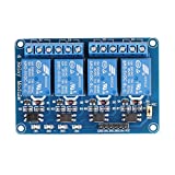 Closed (NC) and a Common, an important convention to note is that when a relay contact is normally open (NO) the relay is not energized.
![]() To configure the relay board with a Raspberry Pi I am assuming that you are running the latest version of Raspian and have the ability to connect to your Pi either through SSH with putty and FTP with filezilla, or directly with a keyboard and monitor, if you haven’t set-up your RPi yet then check out my getting started section.
To configure the relay board with a Raspberry Pi I am assuming that you are running the latest version of Raspian and have the ability to connect to your Pi either through SSH with putty and FTP with filezilla, or directly with a keyboard and monitor, if you haven’t set-up your RPi yet then check out my getting started section.
I will not be connecting AC powered equipment to the output of the relay yet but we will be able to see that we have control by the led indicator lights on the circuit board itself. You could also use a buzzer or multimeter to prove that the relays are switching.
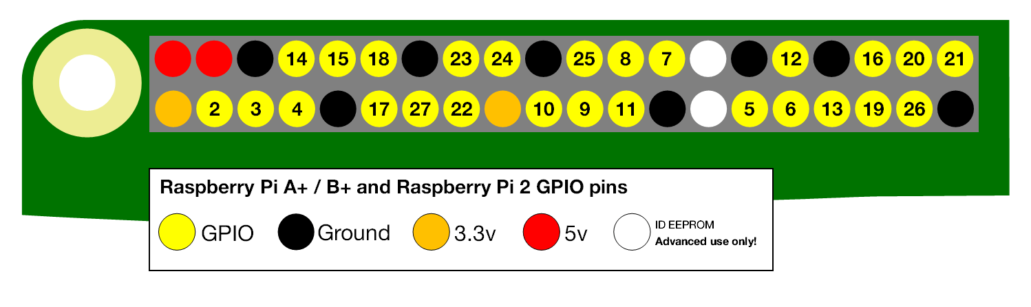
When describing the physical pin connections I will be following the GPIO pin numbering convention show below.
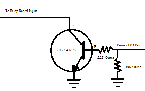
The relay board that I am using is “active low” which means that the relays are switched on when the inputs have 0V connected to them. Since the GPIO pins on the Pi output 3.3V when active we need a way to effectively short the input pins on the relay board to ground when we activate the GPIO pin, the Transistor (2N3904)/Resistor (2.2kΩ, 10kΩ) circuit shown below will achieve this. One of these circuits will be required for each GPIO pin to relay input that you are connecting.
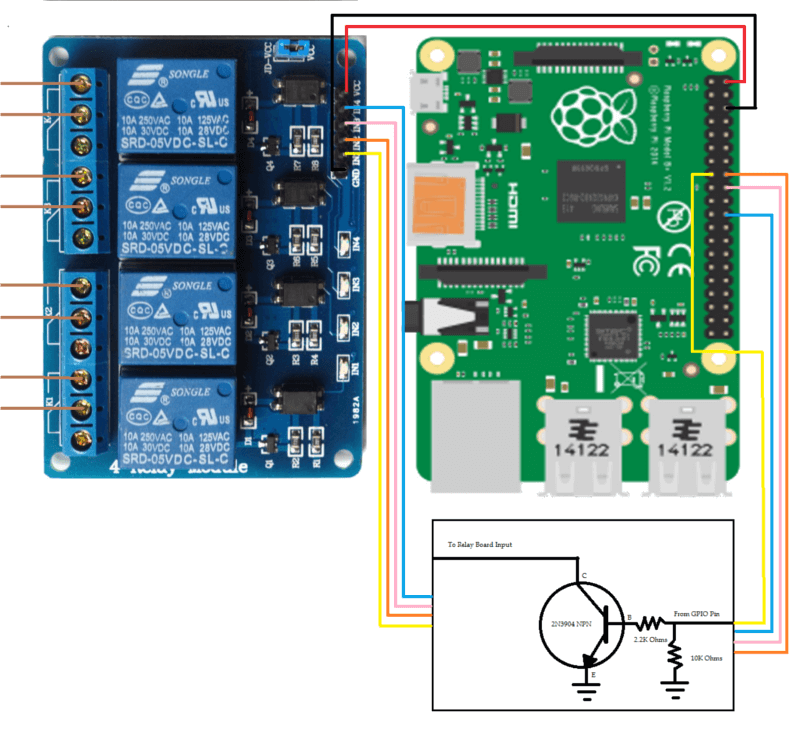
To connect the relay module to your RPi you will need to make the following connections, I’ll be using GPIO pins 22-25 but you can use any spare pins.
- Connect the 5V RPi pin to the Vcc pin of the relay board
- Connect the Ground Pin of the RPi to the Ground pin of the relay board
- Connect GPIO pin 22 to the input of the transistor circuit above and the output to IN1 pin of the relay board
- Repeat the process above for the remaining relays (each relay requires a separate transistor circuit)
- If not connected already then place the jumper between the JD-Vcc and the Vcc pin. (remove if you are using an external 5V power supply for the relay board)
It should be noted that each relay draws approx 72mA from the Pi when activated, given that the Pi itself required 500mA it is important to make sure that your power supply for the Pi can provide this current, a minimum of a 1.5 amp supply should be used to allow for a margin of safety. If you are connecting more than 4 relays then it is probably necessary to power your relay board with a separate 5V supply.
Now that we have a circuit connected we can go ahead and add some code for our Raspberry Pi relay control and test the connections.
#!/usr/bin/env python
import RPi.GPIO as GPIO  # Import GPIO Module
from time import sleep  # Import sleep Module for timing
GPIO.setmode(GPIO.BCM)  # Configures how we are describing our pin numbering
GPIO.setwarnings(False)  # Disable Warnings
OutputPins = [22, 23, 24, 25]  # Set the GPIO pins that are required
#Set our GPIO pins to outputs and set them to off
for i in OutputPins:
    GPIO.setup(i, GPIO.OUT)
    GPIO.output(i, False)
while (True):
# Step through each GPIO pin and set On
    for i in OutputPins:
        GPIO.output(i, True)
# Sleep for 5 seconds
    sleep(5)
# Step through each GPIO pin and set Off
    for i in OutputPins:
        GPIO.output(i, False)
    sleep(5)
We now transfer our code to our chosen folder on the Pi using an FTP client and then run the program. While there is no visible output from the program the led’s and relays should switch on and off every 5 seconds.
To ensure that it is working correctly activate one of the relays so that the led is lit, then using a multimeter check which outputs you have a closed circuit on, shutdown your Pi and the circuit should open. This will ensure that the transistor circuit is working correctly and in the event that your Pi loses power, whatever you are powering from the relay will also turn off.
All the python code is available for both 2.x and 3.x on my Hydropi GitHub Repository.
All going well you have now configured your RPi to interface with a 4-Channel Relay Board.
If you have any thought’s about this article, improvements or errors let me know in the comments below and if you found this helpful, why not share it with others.
At the end of last year I had become interested in the cool things being down with the Raspberry Pi, handheld video games systems, robots, light shows, servers, etc. and I am interested in learning more.
As I read your post I found myself thinking what can you use the relay board for, what projects can you incorporate a relay board in and what can a relay board make a Raspberry Pi do?
Hi Salvatore, I’m using the relay board to switch pool pumps, waterfall pumps and lights at the moment but pretty much any AC powered device that you want to turn on/off remotely you can control.
This is super helpful. Thanks a ton for this. I actually have a relay board and was told that I could actually configure and connect a Raspberry Pi to it. I really didn’t know if that was true or how to do it. But this really did help me with it. Thanks a lot of the helpful information.
Hey Caleb
Really glad that you found this helpful
Hi Dominic,
Can you elaborate a little more on how that transistor and resisters changes a 3.3v output from the gpo pin to a zero single to the relay?
Loving with website by the way!
Rob
Hi Rob
Loosely you can think of the transistor as a switch, when the GPIO pin on the Pi goes HIGH (3.3V) on the Base(B) of the transistor this closes the switch and allows current to flow between the Collector(C) and the Emitter(E) and effectively connects the relay pin to ground(0V), activating the relay. The resistors are there to control the source/sink current so as not to damage the GPIO port. You can see a similar example using a FET rather than an NPN transistor here under Controlling the LED. When it comes to electronic circuits I am still learning myself so I would encourage you to search for a more detailed explanation.
Dom
Thanks for the great explanation. I didn’t realize I should be keeping a max amperage of 3mA through these pins.
Rob
Hey Rob, you can actually draw more than 3mA but it’s really hard to find a definitive answer. From my reasearch you shouldn’t draw more than 16 mA from an individual GPIO or more than 50 mA from the GPIO as a whole, but this dates back to the original Pi, for more info have a look at this.