How to Connect an ORP Sensor to a Raspberry Pi

Knowing the chlorine level of your pool is very important in keeping your pool safe and sanitary. When it comes to pool chemistry though it is the free chlorine level that really matters. Your free chlorine level is what is actually killing the bacteria in your pool and should be maintained at between 1-3 ppm. The free chlorine level can be affected by many factors such as how much the pool is being used, the amount of stabilizer (cyanuric acid) and the pH of the water.
ORP is the acronym for Oxidation Reduction (REDOX) Potential, ORP sensors give the most accurate picture of the effect of all oxidizing and reducing chemicals in your pool. No in-depth knowledge or training is required to obtain accurate repeatable results. User error is virtually eliminated because ORP readings require no subjective, visual interpretation. The World Health Organization (WHO) suggests an ORP value of between 650-720 mV for safe swimming pool water.
The Atlas Scientific ORP sensor is an industrial grade sensor that works well with the Raspberry Pi, it is fully submersible up to the BNC connector in both fresh and saltwater. The sensor can work in serial or via the I2C protocol, for this project you will be configuring the sensor to use the I2C interface on the Pi.
To configure the Pi I am assuming that you are running the latest version of Raspbian and have the ability to connect to your Pi either through SSH with putty and FTP with Filezilla, or directly with a keyboard and monitor if you haven’t set-up your RPi yet then check out my getting started section.
Materials
In this tutorial I will be using the following materials:
- Raspberry Pi (2, 3 or 4)
- Micro SD Card
- Power Supply
- Atlas Scientific ORP Sensor Kit
- Breadboard
- Jumper Wires
- Adafruit T-Cobbler Plus (Optional)
- Raspberry Pi Case (Optional)
The first thing we need to do is enable the I2C modules on the Pi. This is done by entering the following at the command prompt to start the configuration tool
sudo raspi-config
select option 9 – Advanced Options
select option A7 – I2C
select “Yes” for all the questions and reboot the Pi
sudo reboot
After the reboot ensure that all of the Raspbian packages are up to date by running the following commands.
sudo apt update
sudo apt dist-upgrade
sudo apt autoremove
sudo apt clean
Next, check/add the i2c tools package.
sudo apt install i2c-tools
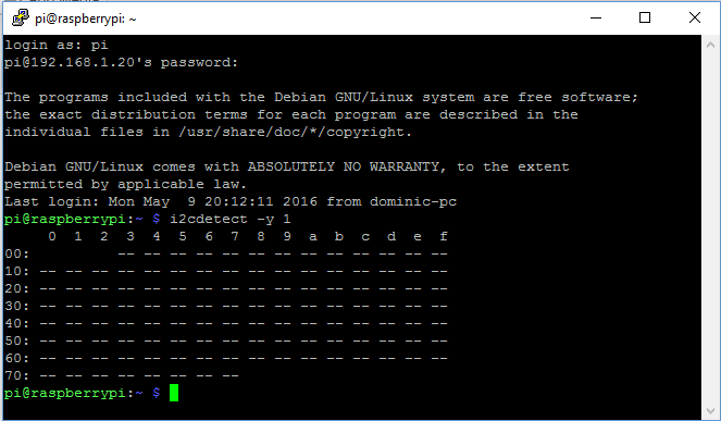
i2cdetect -y 1
This should produce the following without the sensor attached.
Now that we have our I2C module working correctly we can go ahead and connect our ORP sensor.
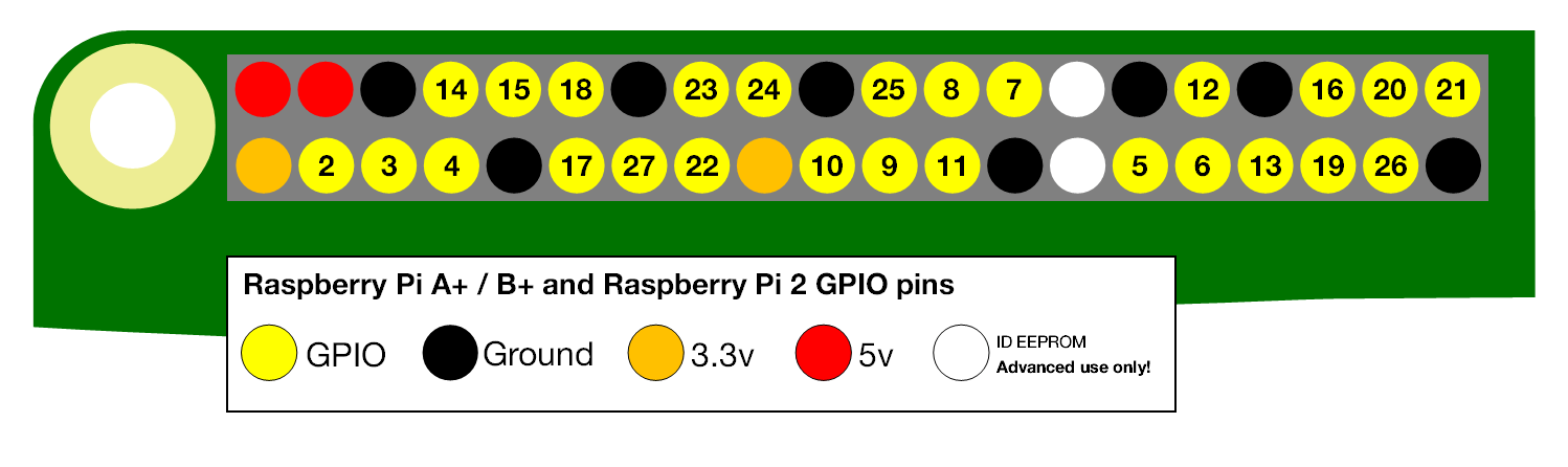
When describing the physical pin connections I will be following the GPIO pin numbering convention shown below.
Firstly we need to get the ORP circuit into the correct mode, when delivered the ORP circuit will be in UART (serial) mode, the ORP circuit has to be manually switched from UART mode to I2C mode. When this is done the ORP circuit will have its I2C address set to 98 (0x62 Hexadecimal).
Using your breadboard perform the following actions
- Cut the power to the device
- Disconnect any jumper wires going from TX and RX to the Pi
- Short the PGND pin to the TX pin
- Power the device
- Wait for LED to change from Green to Blue
- Remove the short from the probe pin to the TX pin
- Power cycle the device
The device is now I2C mode.
The Pi and ORP circuits are now configured so we can go ahead and connect it all together.
Assuming that all of the parts are now mounted on your breadboard
- Connect the GND pin of the ORP circuit to the ground pin of your Pi.
- Connect the TX(SDA) pin to GPIO pin 2.
- Connect the RX(SCL) pin to GPIO pin 3.
Note: Do Not Use jumper wires for these connections or your readings will not be accurate.
- The PRB and PGND pins should be connected via your breadboard to the center and shield pins of your BNC connector.
- Finally, power your ORP circuit by connecting the Vcc pin to the +3.3V pin.
You can now run a quick test to prove that we are set up correctly, from the command prompt enter the following:
i2cdetect -y 1
you should see the following response, if not then check your connections, ensure the light on the ORP circuit is blue and reboot your Pi.
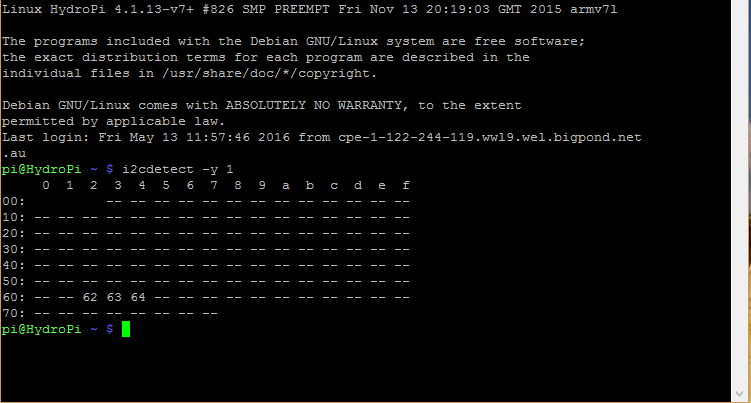
In the image above I have 3 sensors connected to my Pi, the ORP sensor connection is indicated by Hex value 62. The factory pre-set for the ORP sensor is 98 or 62 in hexadecimal as mentioned above, if you have more than 1 ORP circuit connected then you will need to specify a different value. To do this we need to add some python code to our Pi.
Atlas Scientific provides the python code that I will be using here for interfacing with the ORP Circuit.
We start by importing the required python modules
#!/usr/bin/env python
import io  # used to create file streams
import fcntl  # used to access I2C parameters like addresses
import time  # used for sleep delay and timestamps
import string  # helps parse
Next, we add the class code to interface with the ORP circuit (or any other Atlas Scientific circuit for that matter)
class atlas_i2c:
long_timeout = 1.5 # the timeout needed to query readings and
#calibrations
short_timeout = .5 # timeout for regular commands
default_bus = 1 # the default bus for I2C on the newer Raspberry Pis,
# certain older boards use bus 0
default_address = 98 # the default address for the ORP sensor
def __init__(self, address=default_address, bus=default_bus):
# open two file streams, one for reading and one for writing
# the specific I2C channel is selected with bus
# it is usually 1, except for older revisions where its 0
# wb and rb indicate binary read and write
self.file_read = io.open("/dev/i2c-" + str(bus), "rb", buffering=0)
self.file_write = io.open("/dev/i2c-" + str(bus), "wb", buffering=0)
# initializes I2C to either a user specified or default address
self.set_i2c_address(address)
def set_i2c_address(self, addr):
# set the I2C communications to the slave specified by the address
# The commands for I2C dev using the ioctl functions are specified in
# the i2c-dev.h file from i2c-tools
I2C_SLAVE = 0x703
fcntl.ioctl(self.file_read, I2C_SLAVE, addr)
fcntl.ioctl(self.file_write, I2C_SLAVE, addr)
def write(self, string):
# appends the null character and sends the string over I2C
string += "�"
self.file_write.write(bytes(string, 'UTF-8'))
def read(self, num_of_bytes=31):
# reads a specified number of bytes from I2C,
# then parses and displays the result
res = self.file_read.read(num_of_bytes) # read from the board
# remove the null characters to get the response
response = list([x for x in res])
if response[0] == 1: # if the response isnt an error
# change MSB to 0 for all received characters except the first
# and get a list of characters
char_list = [chr(x & ~0x80) for x in list(response[1:])]
# NOTE: having to change the MSB to 0 is a glitch in the
# raspberry pi, and you shouldn't have to do this!
# convert the char list to a string and returns it
return "Command succeeded " + ''.join(char_list)
else:
return "Error " + str(response[0])
def query(self, string):
# write a command to the board, wait the correct timeout,
# and read the response
self.write(string)
# the read and calibration commands require a longer timeout
if((string.upper().startswith("R")) or
(string.upper().startswith("CAL"))):
time.sleep(self.long_timeout)
elif((string.upper().startswith("SLEEP"))):
return "sleep mode"
else:
time.sleep(self.short_timeout)
return self.read()
def close(self):
self.file_read.close()
self.file_write.close()
Finally, we will add our main program
def main():
    device = atlas_i2c()
    # creates the I2C port object,specify the address or bus if
    # necessary
    print(">> Atlas Scientific sample code")
    print(">> Any commands entered are passed to the board via"
          "I2C except:")
    print(">> Address,xx changes the I2C address the Raspberry"
         " Pi communicates with.")
    print(">> Poll,xx.x command continuously polls the board"
          "every xx.x seconds")
    print(" where xx.x is longer than the {} second timeout.".
         format(atlas_i2c.long_timeout))
    print(" Pressing ctrl-c will stop the polling")
    # main loop
    while True:
        myinput = input("Enter command: ")
        # address command lets you change which address
        # the Raspberry Pi will poll
        if(myinput.upper().startswith("ADDRESS")):
            addr = int(myinput.split(',')[1])
            device.set_i2c_address(addr)
            print("I2C address set to " + str(addr))
        # contiuous polling command automatically polls the
        # board
        elif(myinput.upper().startswith("POLL")):
            delaytime = float(myinput.split(',')[1])
            # check for polling time being too short,
            # change it to the minimum timeout if too short
            if(delaytime < atlas_i2c.long_timeout):
                print("Polling time is shorter than timeout, "
                      "setting polling time to {}".
                       format(atlas_i2c.long_timeout))
                delaytime = atlas_i2c.long_timeout
            # get the information of the board you are polling
            info = device.query("I").split(",")[1]
            print("Polling {} sensor every {} seconds, press"
                  "ctrl-c to stop polling".
                      format(info, delaytime))
            try:
                while True:
                    print(device.query("R"))
                    time.sleep(delaytime -
                    atlas_i2c.long_timeout)
            except KeyboardInterrupt:
                # catches the ctrl-c command, which breaks the
                # loop above
                print("Continuous polling stopped")
        # if not a special keyword, pass commands straight to
        # board
        else:
            try:
                print(device.query(myinput))
            except IOError:
                print("Query failed")
if __name__ == '__main__':
    main()
All of this python code is available on my HydroPi GitHub Repository.
We now transfer our code to our chosen folder on the Pi using an FTP client and then run the program.
$ cd your/code/directory
$ python3 your_code.py
The screenshot above shows that we are ready to start sending commands to our ORP circuit, to confirm that the sensor is now fully functioning we will enter the following command
Poll,2.0
This will poll the sensor every 2 seconds and return the result until a ctrl-c command is entered as shown below, to stop the program enter ctrl-c again.
With the sensor now working, there are also a series of other commands that we now have available to us to configure our probe.
Enable/disable the LED on the ORP circuit:
L,1<CR> – LED enable
L,0<CR> – LED disable
L,? <CR> – Query the LED
Take a single reading:
R – Returns a single reading
Calibration:
The ORP circuit can be calibrated using just a single point. Any off the shelf calibration solution can be used
Cal,nnn – Where nnn is an integer or floating point value
Cal,clear – Clears all calibration data
Cal,? – Query the calibration
Circuit Address Change:
I2c,n – n is the new decimal address
Changes to the address of the circuit will cause a loss of connectivity until the python script is restarted with the new address.
Info, Status, Low Power and Factory Reset:
I – Device information
STATUS – Reports reason for last reboot and Vcc voltage
FACTORY – Factory reset. This will not change the communications protocol back to UART.
SLEEP – Enter the low power sleep state.
For more information on the configuration of the ORP circuit read this.
If you would like to see how I have implemented an ORP sensor why not check out my Hydropi overview page which has all the articles related to my own personal project.
There we have it, you have now configured your Pi to interface with the Atlas Scientific ORP Sensor.
If you have any thought’s about this article, improvements or errors let me know in the comments below and if you found this helpful, why not share it with others.
Hi Dominic,
What an interesting article regarding chlorine levels for your pool.
It is imperative that chlorine levels should be maintained at levels to kill the bacteria in your pool for health and safety.
On average how often should you do a chlorine level check with an ORP sensor? and where could I purchase an Atlas Scientific ORP sensor?
Thanks for your time,
Simon.
Hey Simon,
The thing about this system is that it is monitoring your pool 24 hours a day and send’s you an email when the level goes out of range, so you only need to worry about it when you get a notification. If you would like to try it out you can grab one here.
Thanks for your quick response.
That is the type I’m looking for and you’ve pointed me in the right direction.
Thanks again,
Simon.
My pleasure, glad I could help
Can both the ORP and the PH share the same Pins on the Pi?
Hi Matthew
If you are using the I2C bus then multiple sensors can be connected to the I2C pins of the Pi.
How do you calibrate this ORP probe?
Hi
This probe uses a single point calibration method, you need to use a solution like this as a reference and then follow the instructions on page 42 of this document.
Hope this helps
How do you know the amount of chlorine present in the swimming pool? What sensor did you use?
Hi Dennis
There is no specific chlorine senor from Atlas Scientific so the ORP sensor is the next best thing, it measures the oxidizing potential of the chlorine on the pool. A value over 650 indicates that there is sufficient free chlorine in the pool to keep it clean, It’s not a perfect measure as if you have an auto chlorinator it produces Hydrogen ions which can affect the reading, with a pool cover on there is no way for the hydrogen to escape so you will generally see a higher reading. In my experience if you remove the cover the reading will return to normal within about 2 hour.
Hope this helps.
I’m curious if you have any pictures of the physical installation. How are you getting all the probes into the water? Is there a separate custom PVC pipe with holes drilled for the various measurements?
Hi Coby
You can find some pictures here and here. There is also images of the construction available in the overview
Hi Dominic
I’m interested in this project and am getting ready order the ORP kit. Thanks for posting this project – it is just what I was looking to do. Just curious if you’re still running the system and how it’s working? Doesn’t look like you’ve posted in a while. Hope all is well with you!
Hi Brad, Yep the system is still running just haven’t done anything with the website for a while.
Dominic,
I have the hydropi setup with an air temp sensor and ORP sensor right now. I am getting readings from the air temp, but the ORP I continue to get an “error reading orp sensor” in the log file. I can run the Atlas code from their repository and it get readings with the polling function, but for some reason the sensor_manager code is erroring? What am I doing wrong? I installed the i2c-tools. I love this setup, just stuck for a couple days now. Sorry to bother you.
Thanks,
Kurt
Hi Kurt
The Atlas Scientific repository has been updated significantly since I made this, try running the code found on my Github page and see if that shows you why the ORP sensor is returning an error.