Connecting an Electrical Conductivity Sensor to a Raspberry Pi
Raspberry Pi Electrical Conductivity Sensor
If you have a saltwater pool and are using a chlorinator to provide most of the chlorine then knowing the amount of dissolved salt in the water is crucial to maintaining your pools health and safety.
Electrical Conductivity sensors provide a reading in microsiemens, which is a measure of conductance (as opposed to resistance). Using this we can calculate a salinity reading in parts per million(ppm).
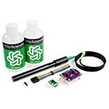
![]() The Atlas Scientific Electrical Conductivity sensor is an industrial grade sensor that works well with the Raspberry Pi, it is fully submersible up to the BNC connector in saltwater. The sensor can work in serial or via I2C protocol, for this project you will be configuring the sensor to use the I2C interface on the RPi.
The Atlas Scientific Electrical Conductivity sensor is an industrial grade sensor that works well with the Raspberry Pi, it is fully submersible up to the BNC connector in saltwater. The sensor can work in serial or via I2C protocol, for this project you will be configuring the sensor to use the I2C interface on the RPi.
To configure the RPi I am assuming that you are running the latest version of Raspian and have the ability to connect to your Pi either through SSH with putty and FTP with filezilla, or directly with a keyboard and monitor, if you haven’t set-up your RPi yet then check out my getting started section.
The first thing we need to do is enable the I2C interface on the RPi. This is done by entering the following at the command prompt to start the configuration tool
select option 9 – Advanced Options
select option A7 – I2C
select “Yes” for all the questions and reboot the RPi
After the reboot connect to the command prompt and enter
sudo apt-get install i2c-tools
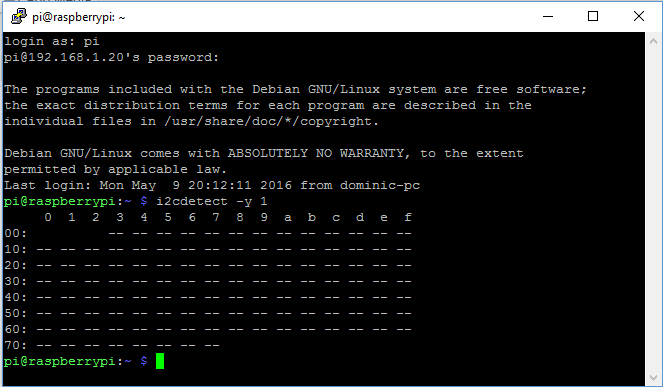
i2cdetect -y 1
This should produce the following without the sensor attached.
Now that we have our I2C module working correctly we can go ahead and connect our EC sensor. The following materials will be needed to get started:
- Raspberry Pi
- Atlas Scientific Electrical Conductivity sensor kit
- Breadboard
- Jumper Wires
- Adafruit T-Cobbler Plus (optional)
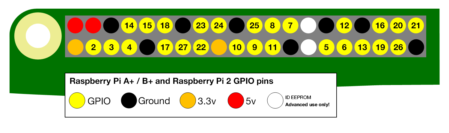
When describing the physical pin connections I will be following the GPIO pin numbering convention show below.
Firstly we need to get the EC circuit into the correct mode, when delivered the EC circuit will be in UART (serial) mode, the EC circuit has to be manually switched from UART mode, to I2C mode. When this is done the EC circuit will have its I2C address set to 100 (0x64 Hexadecimal).
Using your breadboard perform the following actions
- Cut the power to the device
- Disconnect any jumper wires going from TX and RX to the RPi
- Short the PRB pin to the TX pin
- Power the device
- Wait for LED to change from Green to Blue
- Remove the short from the probe pin to the TX pin
- Power cycle the device
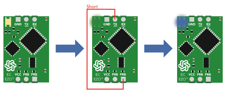
The device is now I2C mode.
The RPi and EC circuit are now configured so we can go ahead and connect it all together.
Assuming that all of the parts are now mounted on your breadboard
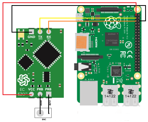
- Connect the GND pin of the EC circuit to the ground pin of your RPi.
- Connect the TX(SDA) pin of the EC circuit to GPIO pin 2.
- Connect the RX(SCL) pin of the EC circuit to GPIO pin 3.
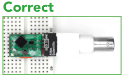
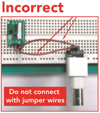
Note: Do Not Use jumper wires for these connections or your readings will not be accurate.
- The 2 PRB pins should be connected via your breadboard to the center and shield pins of your BNC connector.
Note: It makes no difference which way around the pins on the E.C. circuit are connected to the two BNC pins.
- Finally power your EC circuit by connecting the Vcc pin to the +3.3V pin.
You can now run a quick test to prove that we are setup correctly, from the command prompt enter the following:
you should see the following response, if not then check you connections, ensure the light on the EC circuit is blue and reboot your RPi.
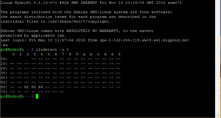
In the image above I have 3 sensors connected to my RPi, the EC sensor connection is indicated by Hex value 64. The factory pre-set address for the EC sensor is 100 or 64 in hexadecimal as mentioned above, if you have more than 1 EC circuit connected then you will need to specify a different value. To do this we need to add some python code to our RPi.
Atlas Scientific provide the python code that I will be using here for interfacing with the EC Circuit.
We start by importing the required python modules
import io  # used to create file streams
import fcntl  # used to access I2C parameters like addresses
import time  # used for sleep delay and timestamps
import string  # helps parse strings
Next we add the class code to interface with the EC circuit (or any other Atlas Scientific circuit for that matter)
class atlas_i2c:
long_timeout = 5 # the timeout needed to query readings and calibrations
short_timeout = 5 # timeout for regular commands
default_bus = 1 # the default bus for I2C on the newer Raspberry Pis
#certain older boards use bus 0
default_address = 100 # the default address for the EC sensor
def __init__(self, address=default_address, bus=default_bus):
# open two file streams, one for reading and one for writing
# the specific I2C channel is selected with bus
# it is usually 1, except for older revisions where its 0
# wb and rb indicate binary read and write
self.file_read = io.open("/dev/i2c-" + str(bus), "rb", buffering=0)
self.file_write = io.open("/dev/i2c-" + str(bus), "wb", buffering=0)
# initializes I2C to either a user specified or default address
self.set_i2c_address(address)
def set_i2c_address(self, addr):
# set the I2C communications to the slave specified by the address
# The commands for I2C dev using the ioctl functions are specified in
# the i2c-dev.h file from i2c-tools
I2C_SLAVE = 0x703
fcntl.ioctl(self.file_read, I2C_SLAVE, addr)
fcntl.ioctl(self.file_write, I2C_SLAVE, addr)
def write(self, string):
# appends the null character and sends the string over I2C
string += "�0"
self.file_write.write(string)
def read(self, num_of_bytes=31):
# reads a specified number of bytes from I2C
#then parses and displays the result
res = self.file_read.read(num_of_bytes) # read from the board
response = filter(lambda x: x != 'x00', res)
# remove the null characters to get the response
if(ord(response[0]) == 1): # if the response isnt an error
char_list = map(lambda x: chr(ord(x) & ~0x80), list(response[1:]))
# change MSB to 0 for all received characters except
#the first and get a list of characters
# NOTE: having to change the MSB to 0 is a glitch
#in the raspberry pi, and you shouldn't have to do this!
return "Command succeeded " + ''.join(char_list)
# convert the char list to a string and returns it
else:
return "Error " + str(ord(response[0]))
def query(self, string):
# write a command to the board, wait the correct timeout
#and read the response
self.write(string)
# the read and calibration commands require a longer timeout
if((string.upper().startswith("R")) or
(string.upper().startswith("CAL"))):
time.sleep(self.long_timeout)
elif((string.upper().startswith("SLEEP"))):
return "sleep mode"
else:
time.sleep(self.short_timeout)
return self.read()
def close(self):
self.file_read.close()
self.file_write.close()
Finally we will add our main program
def main():
    device = atlas_i2c()  # creates the I2C port object, specify the address
                          # or bus if necessary
    print ">> Atlas Scientific sample code"
    print ">> Any commands entered are passed to the board via I2C except:"
    print (">> Address,xx changes the I2C address the Raspberry Pi "
    "communicates with.")
    print (">> Poll,xx.x command continuously polls the board every "
    "xx.x seconds")
    print (" where xx.x is longer than the %0.2f second "
    "timeout." % atlas_i2c.long_timeout)
    print " Pressing ctrl-c will stop the polling"
    # main loop
    while True:
        myinput = raw_input("Enter command: ")
        # address command lets you change which address
        # the Raspberry Pi will poll
        if(myinput.upper().startswith("ADDRESS")):
            addr = int(string.split(myinput, ',')[1])
            device.set_i2c_address(addr)
            print ("I2C address set to " + str(addr))
        # contiuous polling command automatically polls the board
        elif(myinput.upper().startswith("POLL")):
            delaytime = float(string.split(myinput, ',')[1])
            # check for polling time being too short,
            # change it to the minimum timeout if too short
            if(delaytime < atlas_i2c.long_timeout):
                print ("Polling time is shorter than timeout, setting "
                "polling time to %0.2f" % atlas_i2c.long_timeout)
                delaytime = atlas_i2c.long_timeout
            # get the information of the board you're polling
            info = string.split(device.query("I"), ",")[1]
            print ("Polling %s sensor every %0.2f seconds, press ctrl-c "
            "to stop polling" % (info, delaytime))
            try:
                while True:
                    print device.query("R")
                    time.sleep(delaytime - atlas_i2c.long_timeout)
            except KeyboardInterrupt:  # catches the ctrl-c command,
                                       # which breaks the loop above
                print "Continuous polling stopped"
        # if not a special keyword, pass commands straight to board
        else:
            try:
                print device.query(myinput)
            except IOError:
                print "Query failed"
if __name__ == '__main__':
    main()
All of this python code is available for both 2.x and 3.x on my HydroPi GitHub repository.
We now transfer our code to our chosen folder on the RPi using an FTP client and then run the program.
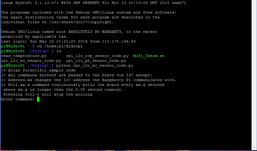
The screenshot above shows that we are ready to start sending commands to our EC circuit, to confirm that sensor is now fully functioning we will enter the following command
This will poll the sensor every 5 seconds and return the result until a ctrl-c command is entered as shown below, to stop the program enter ctrl-c again.
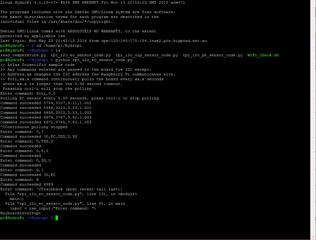
With the sensor now working there are also a series of other commands that we now have available to us to configure our probe.
The EC circuit actually outputs 4 different values in a CSV string, Electrical Conductivity(EC), Total Dissolved Solids(TDS), Salinity(S) and Specific Gravity(SG) as can be seen above. For the purposes of determining the salinity of a pool we will only be using the EC value. The additional commands that can be seen in the print out are explained just below under the title Removing Output Parameters.
Enable/disable the LED on the EC Circuit:
L,1 -LED enable
L,0 – LED disable
L,? – Query the LED
Take a single reading:
R – Returns a single reading
Set the Probe Type:
K,(Any value between 0.1 and 10) – Should be set to the value of your probe (0.1, 1, 10), for this project K1.0 is the correct choice.
K,? – Report the current K value
Temperature Compensation:
To ensure accurate results the probe needs to know the temperature of the liquid it is measuring in °C, factory default is 25°C
T,22.5 – Set the temperature offset value
T,? – Query the set temperature
Calibration:
The EC circuit can be calibrated using a single point or double point reference
Cal,dry – This should always be the first reference point you configure. Probe must be completely dry, as any liquid will affect the result.
Single Point Calibration
Cal,one,n – Used for single point calibration, n is any EC value expressed in microsiemens
Double Point Calibration
Cal,low,n – Used for the double point calibration, n is the low test EC value expressed in microsiemens
Cal,high,n – Used for the double point calibration, n is the high test EC value expressed in microsiemens
Cal,clear – Clears all calibration data
Cal,? – Query the calibration
Removing output parameters:
The EC circuit outputs 4 different values in a CSV string, if you don’t want all of these parameters then some will have to be removed from the output.
O,(parameter),(1 or 0) – Parameter can be any one of the four listed above(EC, TDS, S, SG).To enable the parameter set the second value to 1, to disable set it to 0.
O,? – Displays the enabled/disabled state of each of the parameters.
See image above for examples.
Circuit Address Change:
I2c,n – n is the new decimal address
Changes to the address of the circuit will cause a loss of connectivity until the python script is restarted with the new address.
Info, Status, Low Power and Factory Reset:
I – Device information
STATUS – Reports the reason for the last reboot and the Vcc voltage
FACTORY – Factory reset. This will not change the communications protocol back to UART.
SLEEP – Enter low power sleep state.
If you would like to see how I have implemented the EC sensor why not check out my Hydropi overview page which has all the articles related to my own personal project.
For more information on configuration of the Atlas Scientific EC circuit read this.
There we have it, you have now configured your RPi to interface with the Atlas Scientific EC Sensor.
If you have any thought’s about this article, improvements or errors let me know in the comments below and if you found this helpful, why not share it with others.

This is actually pretty cool, I feel like I could follow these instructions to configure an RPi to interface with an Atlas Scientific EC Sensor.
What do you place it into when you’re done putting it together? How specifically would you put it to practical use?
Another post about these things maybe? ?
Hi Steve,
I actually have it all mounted in a waterproof box and use it to monitor various chemical levels in my pool. I’m slowly documenting all the steps but here’s an overview where you can see pictures of the final installation and the webpage controller.
Dom,
I don’t have a pool so checking chlorine isn’t something I have to do. However, you didn’t lose me as I have a chemistry background and understand what you’re trying to accomplish. It looks like your article accomplishes 2 things: you’re configuring for set-up and then calibrating for use.
Hi Bill
That was the aim of the article, just to explain how to put this part of the project together, here you can see an overview of how it fits into the whole project.
Hi Dominic,
Can you explain the isolation a little further, looks like Atlas has isolators for the probe circuit carriers as well as the power side, do we need one or both? Do we need to put an isolator on all probes and do we need to add isolation due to the EC probe, if we build with just PH, ORP and temp can we remove the isolation? As this is my first attempt I may build this in phases to reduce initial outlay
Hi Dean
The EC probe is the one that causes the problem, if you don’t have an EC probe in your project then you don’t need to add any isolation. If you do then you need to isolate the pH and ORP probes from it. The data lines on the Atlas Scientific isolator marked A and B can be used to isolate UART, I2C or SPI data protocols and the 5V and GND to isolate the power supply. The “IN” side of the board goes to your Pi while the “OUT” is connected to your sensor circuit. The other option is to use the new single circuit carrier board which has built in isolation.
Hope this helps
Hi Dom,
Have you looked at using this information to control the salt generator and maybe main pump run time?
Mal.
Hi Mal,
I actually run the main pump using relays and a MySql configured timer on the Pi, as for controlling the salt/chlorine generator I haven’t done this yet as I have the sensors installed in the plumbing, I have found that the 5 minute readings for the sensors can sometimes jump around. I am only using the sensors at the moment to provide an average as a guide that I then use for manual dosing. I imagine that if the sensors were in the main pool water and giving steady readings then it would be easy enough to program the conditions to activate the SWG only when the ORP dropped and the main pool pump was running.
Regards
Dom
This is great guide! I’m in the process of building one myself.
You mentioned isolating the circuit for other sensors. I would like to add a pH meter to the system as well. I would appreciate any thoughts you have on how to accomplish that.
Hi Richard
If you are adding a pH sensor then you need to isolate that pH sensor from the EC sensor, Atlas Scientific provide a couple of ways of doing this either with a Single Circuit Carrier Board that you simply plug your pH sensor board into or you can use their Inline Voltage Isolator board.
Just to be clear you do not require isolation on the EC sensor but you do need to isolate all other sensors from it.
Hope this helps
Dom
Hey Dom,
I am building a probe with the E.C. sensor and a few other things like temperature and depth. I want to know if you have run into any problems with multiple sensors being used at the same time as the E.C. sensor. I know you talked about isolation, but have there been any other surprises? I see that Atlas mentions a pull-up resistor possibly being necessary on the SCL and SDA lines. Did you put any electronic refinement like that in place?
Hi Matt
When it comes to multiple sensors the only problem I ran into was with the isolation between them. Originally when I built the circuit I did have pull up resistors on the I2C lines, this didn’t really cause any problems but then I learnt that the Pi has 1.8K pull up resistors built in so I removed the external ones as they actually lower the overall resistance because they are in parallel. The Atlas Scientific sensors work really well with the Pi so there was no real need for any external electronic changes.
Good Luck with your project
Dom
Hi.
I’m doing this project.
Do you have a video tutorial on YouTube?
Sorry I haven’t made any videos about this project, hopefully though you can follow what I’ve written.
Good Luck.
Do you know of any cheaper sensors that could be used?
This one has an industrial price tag as well as performance ?
Hi Bill
I know that American Marine make some cheaper pH sensors but i’m not too sure if they make EC sensors, I saw the Atlas Scientific one’s reviewed on Sparkfun, I really liked that they had the full range of the sensors that I wanted and that they had already created some of the code for me. Sorry I can’t be of more help but since choosing these I haven’t really bothered researching anything else.
Hello, I’m having some issues with my setup. I have three EC chips, and I keep getting “string index out of range” errors from the following line:
if(ord(response[0]) == 1): # if the response isnt an error
It is thrown by the def “query” function calling the def “read” function from the following line:
return self.read()
In my code I call the def “query” function with the following bit of code:
I2Cresponse = str(device.query(“R”))
Any ideas about what is happening here? Also, do you know of a work around? It looks like the def “read” is calling a non-numerical character after the numerical reading once in a while which triggers the sting error. Do you know why this happens, and is there a way to salvage the data (i.e. throw out the non-numerical characters at the end) when this happens?
Hi Sam
I’m not 100% sure why you are getting non-numerical characters from the response, I’ll have to investigate further. If it’s only happening sometimes then I simple temporary solution may be to wrap the query in a try/except statement.
try:
I2Cresponse = str(device.query(“R”))
except:
I2Cresponse = 10000
This should ensure that the program continues running even in the event that there is a read failure from the sensor. I’ll try to find out more and give you a better solution.
Can you power multiple atlas scientific integrated circuits using one 3.3v power pin?
The Atlas Scientific sensors draw very little current so yes you can run multiple sensors from the 3.3v power rail, personally I’m running 4 without an issue.
Hi Dominic,
Would this setup work with the EC 2.0/3.0 Legacy circuit as well?
This is what I mean: https://www.atlas-scientific.com/_files/_datasheets/_circuit/EC_Circuit_3.0.pdf
Also, do you know where I could get hold of one (only the circuit I already have a sensor)
Hi Barnabas
The python program I’ve written uses the I2C data protocol on the Atlas Scientific EZO circuits, earlier versions of the board use TTL RS-232 so it wouldn’t be compatible. You can get just the EC circuit directly from the Atlas scientific website or on Amazon.
Hi Dominic
Do you leave the EC probe submerged permanently?
Hi John
Yes, I have the probe installed in the plumbing so that it is always in the water
Hi. why is this mentioned that the sensor cant be read using multimeters or adc? I want to calculate resistivity of water (reciprocal of conductivity) and turn on/off appliances based on the resistivity value using raspberry pi.
Hi Rizwan
That’s the advice from Atlas Scientific.