How to Connect a pH Sensor to a Raspberry Pi
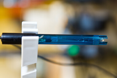
 Whether you want to monitor a pool, aquarium or some other body of water, connecting a pH sensor to a Raspberry Pi can be achieved relatively easily. In this tutorial I’ll be using the Atlas Scientific pH sensor, it’s an industrial grade sensor that works well with the Raspberry Pi, it’s fully submersible up to the BNC connector in both fresh and saltwater. The sensor works using either serial communication or via the I2C protocol, for this example, I will be configuring the sensor to use the I2C interface on the Raspberry Pi.
To configure the Pi I am assuming that you are running the latest version of Raspian, have the ability to connect to your Pi either through SSH with putty and FTP with Filezilla, or directly with a keyboard and monitor. If you haven’t set-up your Pi yet then check out the getting started section.
Materials
In this tutorial I will be using the following materials:
- Raspberry Pi (2, 3 or 4)
- Micro SD Card
- Power Supply
- Atlas Scientific pH sensor kit
- Breadboard
- Jumper Wires
- Adafruit T-Cobbler Plus (Optional)
- Raspberry Pi Case (Optional)
The first thing we need to do is enable the I2C modules on the Pi. This is done by entering the following at the command prompt to start the configuration tool.
sudo raspi-config
select option 5 – Interfacing Options
select option P5 – I2C
select “Yes” for all the questions and reboot the Pi
sudo rebootNote: The GPIO pins 2&3 on the RPi have now been configured as the Serial Data Line (SDA) and Serial Clock Line (SCL) for use by the I2C protocol. The TX connection of the sensor circuit will connect to SDA (pin 2) on the Pi and the RX connection will go to the SCL (pin 3).
After the reboot open the terminal and ensure that all the Raspbian packages are up to date, enter the following
sudo apt update
sudo apt dist-upgrade
sudo apt autoremove
sudo apt clean
Next, check or add the Raspbian i2c tools package
sudo apt install i2c-tools
i2cdetect -y 1
This should produce the following without the sensor attached.
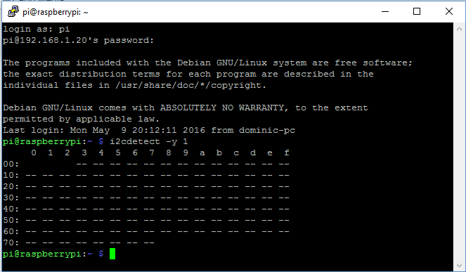
Now that we have our I2C module working correctly we can go ahead and connect our pH sensor.
When describing the physical pin connections I will be following the GPIO pin numbering convention shown below.

Firstly we need to get the pH circuit into the correct mode, when delivered the pH circuit will be in UART (serial) mode, the pH circuit has to be manually switched from UART mode to I2C mode. When this is done the pH circuit will have its I2C address set to 99 (0x63).
Using your breadboard perform the following actions
- Cut the power to the device
- Disconnect any jumper wires going from TX and RX to the Pi
- Short the PGND pin to the TX pin
- Power the device
- Wait for LED to change from Green to Blue
- Remove the short from the probe pin to the TX pin
- Power cycle the device
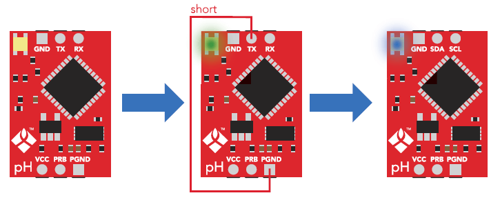
The device is now I2C mode.
The Pi and pH circuit are now configured so we can go ahead and connect it all together
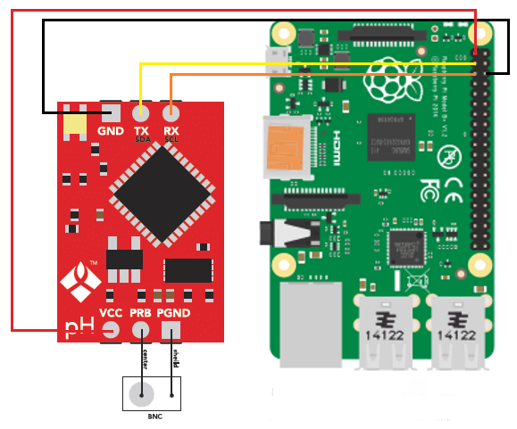
Assuming that all of the parts are now mounted on your breadboard
- Connect the GND pin of the pH circuit to the ground pin of your RPi.
- Connect the TX(SDA) pin to GPIO pin 2.
- Connect the RX(SCL) pin to GPIO pin 3.
Note: Do Not Use jumper wires for these connections or your readings will not be accurate.
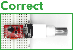
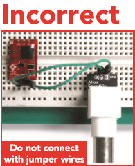
- The PRB and PGND pins should be connected via your breadboard to the center and shield pins of your BNC connector.
- Finally, power your pH circuit by connecting the Vcc pin to the +3.3V pin.
You can now run a quick test to prove that we are set up correctly, from the command prompt enter the following:
i2cdetect -y 1you should see the following response, if not then check your connections, ensure the light on the pH circuit is blue and reboot your RPi.
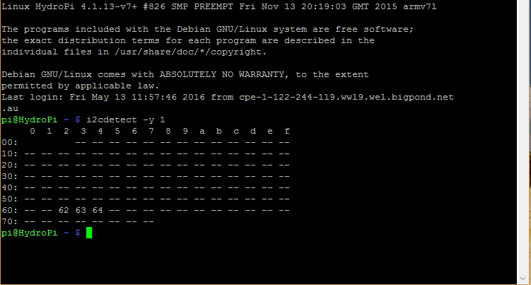
In the image above I have 3 sensors connected to my RPi, the pH sensor connection is indicated by Hex value 63. The factory pre-set address for the pH sensor is 99 or 63 in hexadecimal as mentioned above, if you have more than 1 pH circuit connected then you will need to specify a different value. To do this we need to add some python code to our RPi.
Atlas Scientific provides the python code that I will be using here for interfacing with the pH Circuit.
We start by importing the required python modules
#!/usr/bin/env python
import io  # used to create file streams
import fcntl  # used to access I2C parameters like addresses
import time  # used for sleep delay and timestamps
import string  # helps parse strings
Next, we add the class code to interface with the pH circuit (or any other Atlas Scientific circuit for that matter)
class atlas_i2c:
long_timeout = 1.5 # the timeout needed to query readings and
#calibrations
short_timeout = .5 # timeout for regular commands
default_bus = 1 # the default bus for I2C on the newer Raspberry Pis,
# certain older boards use bus 0
default_address = 99 # the default address for the pH sensor
def __init__(self, address=default_address, bus=default_bus):
# open two file streams, one for reading and one for writing
# the specific I2C channel is selected with bus
# it is usually 1, except for older revisions where its 0
# wb and rb indicate binary read and write
self.file_read = io.open("/dev/i2c-" + str(bus), "rb", buffering=0)
self.file_write = io.open("/dev/i2c-" + str(bus), "wb", buffering=0)
# initializes I2C to either a user specified or default address
self.set_i2c_address(address)
def set_i2c_address(self, addr):
# set the I2C communications to the slave specified by the address
# The commands for I2C dev using the ioctl functions are specified in
# the i2c-dev.h file from i2c-tools
I2C_SLAVE = 0x703
fcntl.ioctl(self.file_read, I2C_SLAVE, addr)
fcntl.ioctl(self.file_write, I2C_SLAVE, addr)
def write(self, string):
# appends the null character and sends the string over I2C
string += "�"
self.file_write.write(bytes(string, 'UTF-8'))
def read(self, num_of_bytes=31):
# reads a specified number of bytes from I2C,
# then parses and displays the result
res = self.file_read.read(num_of_bytes) # read from the board
# remove the null characters to get the response
response = list([x for x in res])
if response[0] == 1: # if the response isnt an error
# change MSB to 0 for all received characters except the first
# and get a list of characters
char_list = [chr(x & ~0x80) for x in list(response[1:])]
# NOTE: having to change the MSB to 0 is a glitch in the
# raspberry pi, and you shouldn't have to do this!
# convert the char list to a string and returns it
return "Command succeeded " + ''.join(char_list)
else:
return "Error " + str(response[0])
def query(self, string):
# write a command to the board, wait the correct timeout,
# and read the response
self.write(string)
# the read and calibration commands require a longer timeout
if((string.upper().startswith("R")) or
(string.upper().startswith("CAL"))):
time.sleep(self.long_timeout)
elif((string.upper().startswith("SLEEP"))):
return "sleep mode"
else:
time.sleep(self.short_timeout)
return self.read()
def close(self):
self.file_read.close()
self.file_write.close()
Finally, we will add our main program
def main():
    device = atlas_i2c()
    # creates the I2C port object,specify the address or bus if
    # necessary
    print(">> Atlas Scientific sample code")
    print(">> Any commands entered are passed to the board via"
          "I2C except:")
    print(">> Address,xx changes the I2C address the Raspberry"
         " Pi communicates with.")
    print(">> Poll,xx.x command continuously polls the board"
          "every xx.x seconds")
    print(" where xx.x is longer than the {} second timeout.".
         format(atlas_i2c.long_timeout))
    print(" Pressing ctrl-c will stop the polling")
    # main loop
    while True:
        myinput = input("Enter command: ")
        # address command lets you change which address
        # the Raspberry Pi will poll
        if(myinput.upper().startswith("ADDRESS")):
            addr = int(myinput.split(',')[1])
            device.set_i2c_address(addr)
            print("I2C address set to " + str(addr))
        # contiuous polling command automatically polls the
        # board
        elif(myinput.upper().startswith("POLL")):
            delaytime = float(myinput.split(',')[1])
            # check for polling time being too short,
            # change it to the minimum timeout if too short
            if(delaytime < atlas_i2c.long_timeout):
                print("Polling time is shorter than timeout, "
                      "setting polling time to {}".
                          format(atlas_i2c.long_timeout))
                delaytime = atlas_i2c.long_timeout
            # get the information of the board you are polling
            info = device.query("I").split(",")[1]
            print("Polling {} sensor every {} seconds, press"
                  "ctrl-c to stop polling".
                      format(info, delaytime))
            try:
                while True:
                    print(device.query("R"))
                    time.sleep(delaytime -
                    atlas_i2c.long_timeout)
            except KeyboardInterrupt:
                # catches the ctrl-c command, which breaks the
                # loop above
                print("Continuous polling stopped")
        # if not a special keyword, pass commands straight to
        # board
        else:
            try:
                print(device.query(myinput))
            except IOError:
                print("Query failed")
if __name__ == '__main__':
    main()
All the python code is available on my Hydropi GitHub Repository.
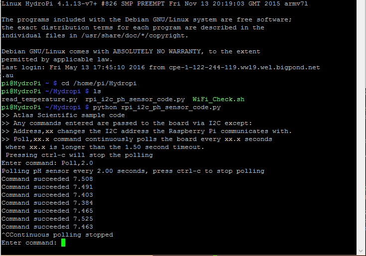
We now transfer our code to our chosen folder on the Pi using an FTP client and then run the program.
$ cd your/code/directory
$ python3 your_code.py
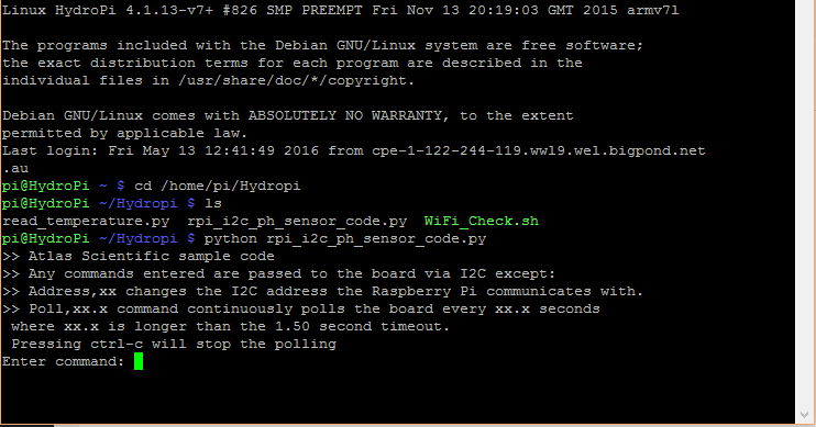
The screenshot above shows that we are ready to start sending commands to our pH circuit, to confirm that the sensor is now fully functioning we will enter the following command
Poll, 2.0
This will poll the sensor every 2 seconds and return the result until a ctrl-c command is entered as shown below, to stop the program enter ctrl-c again.
Warning: If you are using an Electrical Conductivity (EC) sensor in your project then it is important to electrically isolate other sensors from it, this can be done using an Atlas Scientific Electrically Isolated Carrier Board on each of the circuits.
The EC circuit discharges a small electrical current into the water. This small current creates an interference field that can be detected by devices such as the pH probe which may make your readings inaccurate.
With the sensor now working, there are also a series of other commands that we now have available to us to configure our probe.
Enable/disable the LED on the pH circuit:
L,1 – LED enable
L,0 – LED disable
L,? – Query the LED
Take a single reading:
R – Returns a single result
Temperature Compensation:
To ensure accurate results the probe needs to know the temperature of the liquid it is measuring in °C, the factory default is 25°C
T,22.5 – Set the temperature offset value
T,? – Query the set temperature
Calibration:
The pH circuit allows for calibration of either 1,2 or 3 points, pH 7.00 must be performed first and is known as the mid calibration point. There are 2 other points available known as low and high.
Cal,mid,X.XX – Where X.XX represents the pH midpoint. In most cases this should be 7.00
Cal,low,X.XX – Where X.XX represents a low calibration point (pH 1 to pH 6)
Cal,high,XX.XX – Where XX.XX represents a high calibration point (pH 8 to pH 14)
Cal,clear – Clears all calibration data
Cal,? – Query the calibration
Circuit Address Change:
I2c,n – n is the new decimal address
Changes to the address of the circuit will cause a loss of connectivity until the python script is restarted with the new address.
Info, Status, Low Power and Factory Reset:
I – Device information
STATUS – Reports reason for last reboot and Vcc voltage
FACTORY – Factory reset. This will not change the communications protocol back to UART.
SLEEP – Enter a low power sleep state.
Note: Any command sent to the pH circuit will wake it but 4 readings should be taken before considering them to be accurate.
If you would like to see how I have implemented a pH sensor why not check out my Hydropi overview page which has all the articles related to my own personal project.
For more information on configuration of the Atlas Scientific pH circuit read this.
There we have it, you have now configured your RPi to interface with the Atlas Scientific pH Sensor.
If you have any thought’s about this article, improvements or errors let me know in the comments below and if you found this helpful, why not share it with others.

I think I’ll be printing this entire article! Thank you so much for providing so many details in these instructions, and I’m ashamed to say I really like (and need!) the pictures! I will be checking out the rest of your website for more useful information and tips. You really are thorough – I appreciate it so much Thank you!
Thanks Debra, glad you found it helpful
Hi Dominic,
many thanks for this great description (and the others you have written). You have a great way of concentrating to the important things and leave the rest.
I have one question:
You wrote the code for python 2. I’m just writing a python 3 project (control of a fish tank) and would like to integrate pH and EC. But up to now, I always failed to read out pH and EC from my EZO cards (python 2 works fine). Would it be possible for you to provide your code in python 3? I tried to convert it, but due to my very limited knowledge I didn’t manage to do so. I even asked Atlas scientific to provide phython 3 examples, but they have not been helpful. I would be sooooo grateful, if you could help.
Even if you don’t find the time for this, I appreciate your work a lot – PLEASE don’t stop!!
many thanks from Germany
Frank
Hi Frank
I’m just learning when it comes to python too, I basically used the code from Atlas Scientific. I had a go at converting the code and I think the scripts should now run on Python 3. You can find the updated code here and a screenshot of the output I got here. The updated code should also work for your EC sensor. Let me know if they work for you or if you find any errors.
Dom
Hi Dominic
your py3 code works fine. I’m so greatfull for your help. Now it should be easy to integrate pH and EC into my project.
Many, many thanks!!!!!!
Frank
No worries Frank, glad I could help
Hi Dominc,
I have a remark on your description on how to connect the EZO card to the pi:
It is also possible to supply the EZO cards with 3.3V. Then you will not need the resistors. As far as I see it, they are meant to be termination resistors when you run it on unterminated systems. But bus termination is provided on the pi board itself. When you use the 5V, they of course limit your VCC (probably you will toast your raspi when you use 5V without them).
Anyway – I use 3,3V without resistors and it works fine (up to now ? )
many thanks again for your help
Frank
Hi Frank
You’re right the EZO cards will work with voltages from 3.3V-5V and the I2C pins on the Pi also have built in 1.8K pull-up resistors to 3.3V. When I first built this I was unaware of the built in resistors and given that my relay board required a 5V input I decided to keep it consistent. I think I might go back change them to 3.3V just to minimise the risk of doing damage to the Pi.
Dom
Thank you for the wonderful writeup. I bought the PH kit today and tried to get it all up. but i am only getting query failed. I set the address to 63 in the file and the color of the led is blue. Can you help me out.
Hi Natesh
As I can’t see your setup this is just a guess but you mention that you have set the address to 63 in the file, I think you may have a hexadecimal/decimal addressing problem. The Atlas Scientific pH circuit comes from the factory with an I2C address of hexadecimal 63 (which in decimal is 99), try changing where you set the address to 63 in the file to 99 as see if this solves the problem.
If that doesn’t help then you will need to check the i2c address of the pH circuit itself, a quick way to check is to perform the following command
i2cdetect -y 1
you should see 63 in the list, if you see 3F in the list then you have set the pH circuit address to hexadecimal 3F/decimal 63. If this is the case then run the pH sensor python program and enter the following command
I2c,99
This will set the address to decimal 99 (hexadecimal 63), restart the python program and hopefully this will fix the problem.
Finally if you actually want the pH circuit to have a decimal address of 63 then change this line in the python script
def main():
device = atlas_i2c()
to
def main():
device = atlas_i2c(63)
This will force the program to use your set address and not the default one.
let me know if this helps
You are awesome Dominic. You were right to the point. It showed as 63 in the i2cdetect -y 1. I changed the value back to 99 and it all worked perfectly fine. Thank you so much. I will now check how you are reading the data and storing in the database. I will keep bugging you for help :).
Glad I could help Natesh, I’ll update the post and try to highlight the hexadecimal vs decimal values.
Hi Dominic,
I have another query now. I have connect i2c temperature as well to check the water temp. I have connected ORP,PH,EC and Temp. I have isolation board for ORP and PH. My EC reading are erratic. EC and TDS is not the same value. Do i need to add isolation board for EC as well?
Best Regards,
Natesh
Hi Natesh,
It may be necessary to isolate the power to the EC circuit, you can test if electrical noise is causing the problem by placing the probe in a cup of water on it’s own. Disconnect the other probes from their circuits and see if the erratic readings still occur. If that fixes the problem then you will need to add isolation to the circuit. I realize now re-reading my post that I probably could have made that clearer, I’ll look at updating the article.
Dear Dominic,
Thank you. Looks like the probes where not calibrated. Now it looks ok. I have another query. In the EC values we get EC,TDS,Salinity,SG. what i read in the internet is that Ec and TDS are the same. But the reading are different why?
Hey Natesh
TDS looks at all dissolved solids in the water and incorporates both conductive and non-conductive particles which is where the main difference occurs, EC only measures the conductive particles.
Hi Dominic. i found it is very useful for my project! But one question, how can we work our Pi with two atlas scientific sensors (e.g EC and pH) on it? Thanks!
Hi Max
If you have more than one sensor you just connect the I2C pins of each sensor in parallel to the Pi, when you take a reading only the sensor with the requested address will respond.
Hope this helps.
Hi, I congratulate you for the PH project.
Can you tell me if you can put a CURL call in the .py code?
I must send the ph data in real time to this CURL syntax call:
Curl
-i
-H “Accept: application / json”
-H “Content-Type: application / json”
-H “hash: 364957854”
-H “device_id: 100000000000001”
-H “thing_id: 215”
‘Http://mywebsite.it/api/save.php?ph=X’
Thank you and kind.
Hi Rocco
I’ve never written any CURL commands so I’m not to familiar with the syntax, I do know that there’s a python library called pycURL that you can import which might be useful. Sorry that I can’t be of more help.
Hi Dominic,
Ok but sensor data is written in some raspberry folder more?
(Local archive)?
Can not send them on their site with a command in the script?
My process for reading,storing and presenting the pH data is that the python script reads the sensor every 5 min, stores the result in a MySQL database, then using php, the webpage interrogates the database to get the values it needs. The reading is stored as a temporary variable before being sent to the database so you may be able to redirect that to a webpage. As I said before I haven’t used CURL so I am not sure what python commands you would use to send the data straight to your webpage, Stack Overflow may be a better place to ask this question, there are plenty of people there much smarter than I am that could help.
Ok but can polling always be set (in process while) at 2 seconds in the script ??
The minimum time that can be set to take a reading from the Atlas pH probe is 1.5 sec (set in this line of code long_timeout = 1.5), if you wish you can set this to your required polling period or add a sleep function to the code to achieve longer delays.
Ok then the script is capable of running at 1.5 seconds always keep background on raspberry pi ?? The ph value where it is written, where it is in raspberry pi ??
Hi Rocco
This python code reads the value from the sensor and stores it in memory as a variable, that variable is then printed to the screen, the next reading over-writes the value of the variable in memory, the previous reading is not stored anywhere permanently. If you want to store the values you need to write code to send the variable value to a database or save it to a file, it all depends on what you are trying to achieve, if you email me directly through my contact page I might be able to give you more detailed answers.
Hello, and thank you for a really nice blog!
I have i question about the physical installation of the ph and orp sensors. How have you installed them in your pipes, and have you experienced any problem with mounting them in the direct flow of the circulation?
Thanks again, best regards
Mikael Svensson
Sweden
Hi Mikael
You can see from this picture how I have mounted the sensors, I would have preferred to put them in the pool but distances made this impractical. I find that the readings in the plumbing can jump around a little compared to having them directly in the pool but by averaging out the readings it works well.
hi Dominic,
nice work have you done !!!
i have a question.
how can i read 3 sensors and put the results in 3 variables?
my system should be a headless system that send the values every hour to a webserver.
thx for help
ps: python is not my favorit language ( same like english ;-)), sorry for that
greetings from Austria
Mike
Mike
The sensors readings are all stored in a dictionary with the variable name “all_curr_readings” and can be found in “def read_sensors()”. This variable is sent to “def log_sensor_reading()” to load them into the database but there’s no reason you couldn’t send the variable to a webserver or save them as individual variables.
For example in my case when I print the variable “all_curr_readings” I get the following result:
[[‘ds18b20_temp’, 9.1], [‘atlas_temp’, 11.5], [‘ph’, 6.77], [‘orp’, 817.0], [‘ec’, 4612.1]]
if you want to save the individual values to separate variables then try something like this for each value you want to send:
sensor = (all_curr_readings[‘ph’])
print (sensor)
The output will be 6.77
Hope this helps
Hey, Dominic,
I see you have done impressive project
i have a question.
Can I know what the model of the pH sensor you use in this project. Thanks
Hi Zack
I used the Atlas Scientific pH sensor kit for this project with a carrier board
Thanks a lot. This is exactly what I wanted. I have a question though. Can I use a voltage source to change from UART to I2C? Would that be 3.3V or 5V?
Hi Dena
The Atlas scientific circuits work with both 3.3V and 5V so when you are changing the data protocol you can use either.
This is exactly what I wanted. Awesome job.
I have two small queries though.
1. Can I use an external voltage source for the Vcc when I change from UART to I2C?
2. I also plan to use raspberry pi 3 in I2C mode of course. Can I use an SD card to record data? Thanks again!
While not something I have tried it does seem possible to store your data on an external drive by changing the file, /etc/mysql/my.cnf. Try following these instructions. As I said before the sensors will work with either 3.3V or 5V when setting the data protocol to I2C.
Hope this helps.
Hi Dom,
I’m using your instructions to set up my DO sensor. When I enter the “Poll,2.0” command, I’m getting an IOError. It says, “IOError:[Errno 121] Remote I/O error”. Any thoughts?
Thanks!
Hi Dena
I haven’t actually worked with the DO sensors but does it produce a result with a simple read “r” command? If not it sounds like an i2c connection problem, run “i2cdetect -y 1” and confirm that you see the DO sensor, if it’s still default you should see Hex value 61 (Decimal 99).
Thanks, I could connect and get reading from the sensor. Now, I want to add EC, pH and ORP to the raspi. Do you have any article with instructions for connecting multiple sensors? I’m using the purple voltage isolators from Atlas scientific and I am a bit unsure about the pin connections.
I haven’t written an article on connecting multiple sensors but if you’re using the Atlas Scientific isolators then you need to connect the power (3.3 or 5V) from the Pi to the +ve and gnd pins on the IN side of each isolator, the OUT side of the isolator is then taken to power the sensor circuits. The I2C connections are similar as you connect from the Pi to pins A and B on the IN side of your first isolator and then connect the other 3 isolators IN side pins in parallel. The A and B OUT side pins are then connected to each sensor circuit, I just used a small 30 line breadboard to make the connections easily. Note that the I2C addresses on each sensor need to be different for this setup to work.
I’m assuming the 3.7 V end of the isolator as the OUT end and the Vcc end as the IN end is what you mean. Also, regarding the I2C connections, I will have multiple Rx and Tx pins from the 4 isolators (which is essentially the sensor data). How do I connect them to the Raspi SDA and SCL pins?
Hi Dena
The isolators that I use are an older version from Atlas Scientific and have slightly different markings on them, on the latest ones you are correct, the 3.7v side is the isolated output and the Vcc side is the un-isolated input. As for the I2C connections they need to be in parallel so connect the TX(SDA) pin of your first sensor to the TX(SDA) pin of the the 2nd sensor, then from the 2nd sensor TX(SDA) pin to the 3rd sensor TX(SDA) pin and so on until the final sensor TX(SDA) pin connects back to the SDA pin on your Pi. Follow the same process for the RX(SCL) pins and connect the final one back to the SCL pin on your Pi.
Hi
I have reached up till step of configuring it to i2c mode , I want to know what is next step and how program is run ?
Hi Sultan
If you’ve got your pH sensor successfully set to I2C mode then you are pretty much there, the python program on this page is broken into 3 parts to try and highlight the different sections, you can find all the program together here. To run the program from your Pi open up a terminal window, move to the folder (eg. home/pi/myscripts/) that you saved the program in and enter the following – python rpi_i2c_ph_sensor_code.py, assuming that you saved it using the same name the program should now execute, enter a command like Poll,2.0 and the program should start reading your sensor and outputting the results.
Good luck
Hey, I kinda have this different ph sensor, with the 6 pins aligned, I’m new to raspberry, will this code work for me too ?
Hi Ramiz
The code was written for the Atlas Scientific sensors so my first guess would be probably not but without knowing anything about you sensor it’s hard to tell.
This is such an incredibly, well-documented guide. Even better than Atlas Scientific’s PDF guides, and I used it for a DO sensor Keep it up!
Thanks Ellie
Hi Dominic,
Many thanks for documenting all this – I have just finished building one to monitor water quality in our pool using Atlas temp., pH and ORP sensors and a RPi 3B+ running Fedora Server 30 aarch64. Everything is going well with the sensors themselves, apart from some anomalous readings on pH.
I did a 3-point calibration using Atlas reference solutions and the sensor is connected to an isolated channel on a Tentacle T3 board. Initially the readings look plausible, but then fall to around 4.9 – which for our pool is completely impossible. I took everything out yesterday and tested pH using the ref. solutions (pH 4, 7 and 10) as well as various other well-known solutions (conc. sulphuric acid, bicarb, vinegar etc.) and the readings were exactly what I expected. The sensor measured the pool water at pH 6.7, which is a bit on the low side but in line with other test kits. However in the day or so since then measured pH has fallen to 6.25 and still going down – we haven’t added any water balancing chemicals and there is nothing else going on that could cause that big a change. We also have an ORP sensor connected to the other isolated channel but that is working fine, and disconnecting it makes no difference to pH.
One possibility might be the orientation of the sensor. I did the calibration and re-testing with it vertical i.e. tip pointing down, but it is mounted in a 1.5″ T-connector with the tip pointing almost straight up (I would show a photo but can’t upload). There is quite a large bubble in the tube – as is normal AFAIK – which in that orientation floats right to the top. The Atlas datasheet talks about how to move the bubble but doesn’t specifically mention orientation.
Has anyone else had the same problem, and/or know for certain whether the pH probecan be used in this orientation? NB: The tip is always kept wet as it is directly in the main pipe from the pump, so that is not an issue.
Thanks,
Andrew
Hi Andrew
To be honest, this problem is a bit beyond my knowledge, I suggest that you get in contact with the Atlas Scientific Support people and they may be able to advise you on orientation issues.
Hello,
Firstly, great web page, lots of good info. Thanks,
A newbie question, I have the PH sensor kit from Atlas and have now ordered the ORP kit as well. But how to wire 2 of them, do both of them go into the same GPIO (pin 2-3), or can one use any GPIO ?
Thanks in advance.
Regards
Jone
Hi Jone
Yes, you need to connect both sensors to pins 2 and 3 as these are the I2C connections on the Pi. To get both sensors working at the same time connect them in parallel using a breadboard.
Hope this helps
Good luck
HI Dominic, I’m trying to connect a TDS sensor to my Rapsberry pi instead of a ph-sensor, do you reckon it would be much different, TDS sensors give a digital output
Hi Jude
I’ve only really looked at the I2C Atlas sensors in this project, how easy it is to connect your TDS to the Pi will depend on the TDS and the digital output that it produces.
Sorry I can’t be of more help.
Hi Dominic,
Love the post. This is the closest I have seen to what I would like for my project. I am looking for sensor for detecting nutrients like the following:
Protein (g) Carbohydrate (g) Total Sugar (g) Total Fat (g) Saturated Fat (g) Monounsaturated Fat (g) Polyunsaturated Fat (mg) Cholesterol (mg) Calcium (mg) Iron (mg) Sodium (mg) Potassium (mg) Magnesium (mg) Phosphorus (mg) Vitamin A (RAE) Lycopene (mcg) Folate (DFE)
Hi Dominic,
Its a bit tricky sourcing your exact parts in my country.
will this be a decent substitute?
https://www.banggood.com/PH-Value-Data-Detection-and-Acquisition-Sensor-Module-Acidity-and-Alkalinity-Sensor-Monitoring-and-Control-p-1547652.html?rmmds=search&ID=532942&cur_warehouse=CN
Hi Craig
Unfortunately no, the program that I have described above uses the I2C protocol to communicate, the part that you have listed uses “analog voltage signal output” which would require a different program and possibly some additional parts.
This is great, thank you. I am using python3. I saw an earlier comment about new code but the code here looks updated as far as I can tell. My issue is the same as the original post. I modified the sample code from Atlas and used their AtlasI2C class. Every time I try a query or write operation, I get a ERRNO5: IO Error. It happens at self.file_write.write(bytes(cmd, ‘UTF-8’))
I previously had it encoding with ‘latin-1’ which is how it’s done in the sample code. Any ideas what is going on?
Hi Marshall
Not too sure what the issue here is but the code on Github works for me, I should note that the firmware version on my sensor is 1.9, Atlas Scientific have update this over the years.